
Looking at the box, those chamfers on vertical corners could be a bit better. With round things like these corners are, you should try to chmafer it so the distance between each two edges is same. Alternative way to do round things with so many sides is to make a cylinder and weld quarter of it to the box
[WIP] FMK-1 & FMK-3 Mines (PR:F)
-
lucky.BOY
- Posts: 1438
- Joined: 2010-03-03 13:25
Re: [WIP] FMK-1 & FMK-3 Mines (PR:F)
The handle should certaionly have more sides than the rope. While I agree that the number of sides the rope has can stay like this for 1p mesh, it should really be 6-8 for 3p mesh. But really give that handle more sides, about 16 should work. While the handle can be obscured by hand, animator may feel like showing it, so its best to give it same detail as rest of the thing, dont you think 
Looking at the box, those chamfers on vertical corners could be a bit better. With round things like these corners are, you should try to chmafer it so the distance between each two edges is same. Alternative way to do round things with so many sides is to make a cylinder and weld quarter of it to the box
Looking at the box, those chamfers on vertical corners could be a bit better. With round things like these corners are, you should try to chmafer it so the distance between each two edges is same. Alternative way to do round things with so many sides is to make a cylinder and weld quarter of it to the box
-
Rhino
- Retired PR Developer
- Posts: 47909
- Joined: 2005-12-13 20:00
Re: [WIP] FMK-1 & FMK-3 Mines (PR:F)
Indeed, larger and has a bigger silhouette which you can more easily see etc.lucky.BOY wrote:The handle should certaionly have more sides than the rope. While I agree that the number of sides the rope has can stay like this for 1p mesh, it should really be 6-8 for 3p mesh. But really give that handle more sides, about 16 should work. While the handle can be obscured by hand, animator may feel like showing it, so its best to give it same detail as rest of the thing, dont you think

-
3===SPECTER===3
- Posts: 831
- Joined: 2007-05-05 01:13
Re: [WIP] FMK-1 & FMK-3 Mines (PR:F)
[quote=""'[R-DEV"]Rhino;1922860']
Got it I just upped the handle to 16 sides. I'm terrible at knowing how many sides to start with for things
  I also made it a little bigger as per the refs.
I also went ahead and shortened the FMK-1. It still looked too big in comparison to the FMK-3.
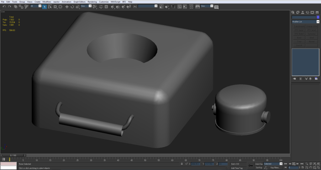
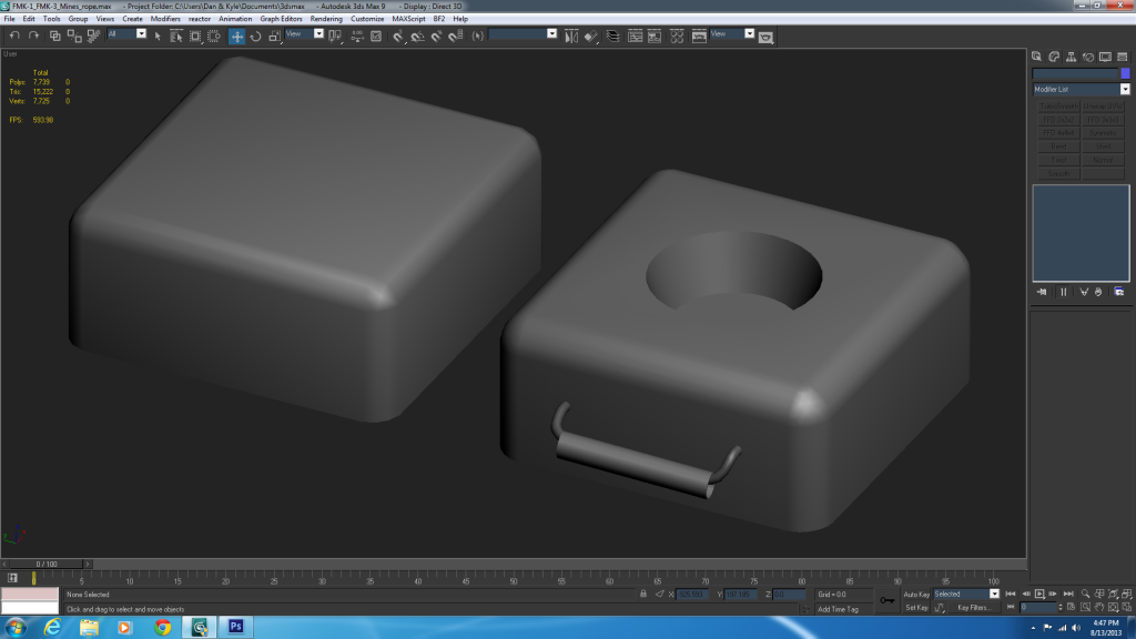
So here's everything all together:
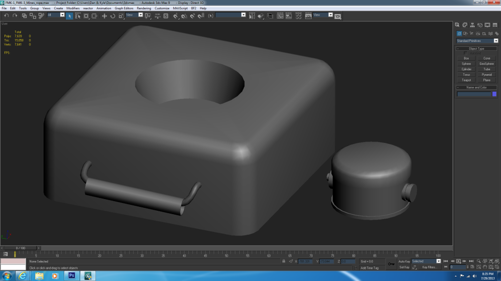
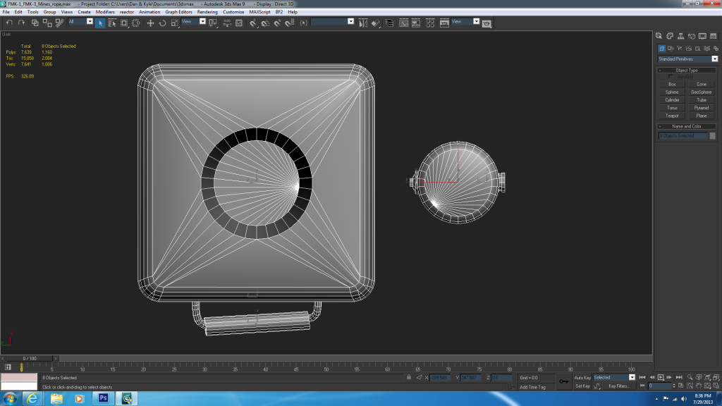
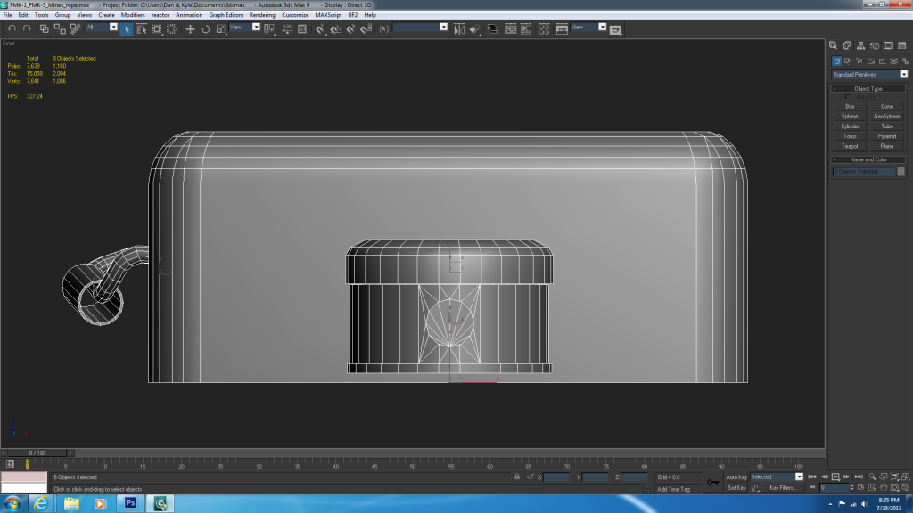
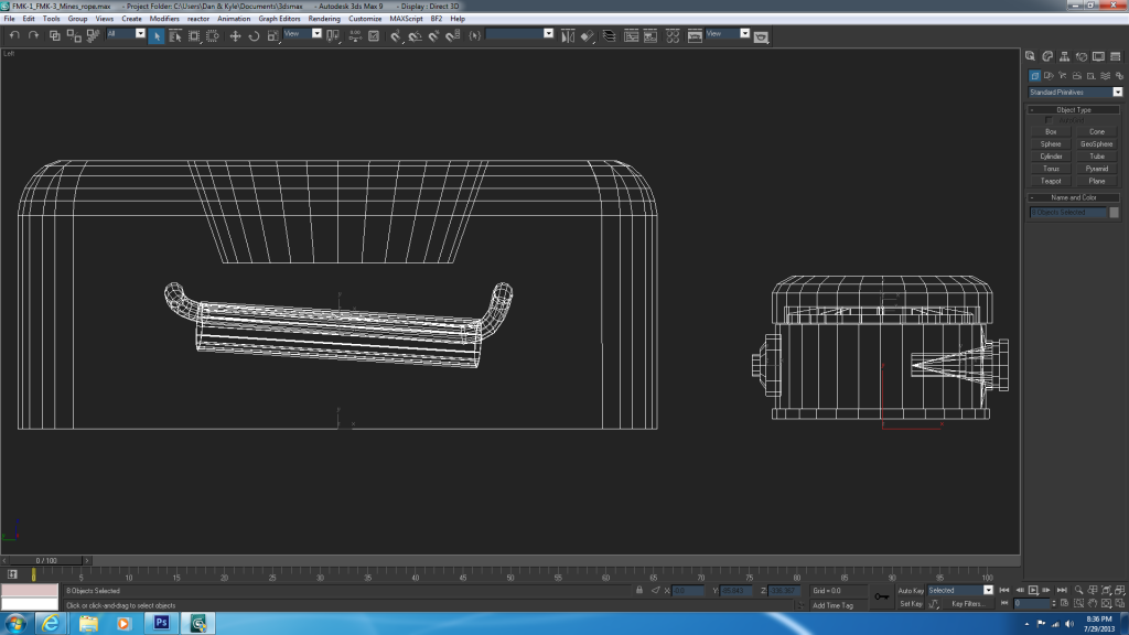
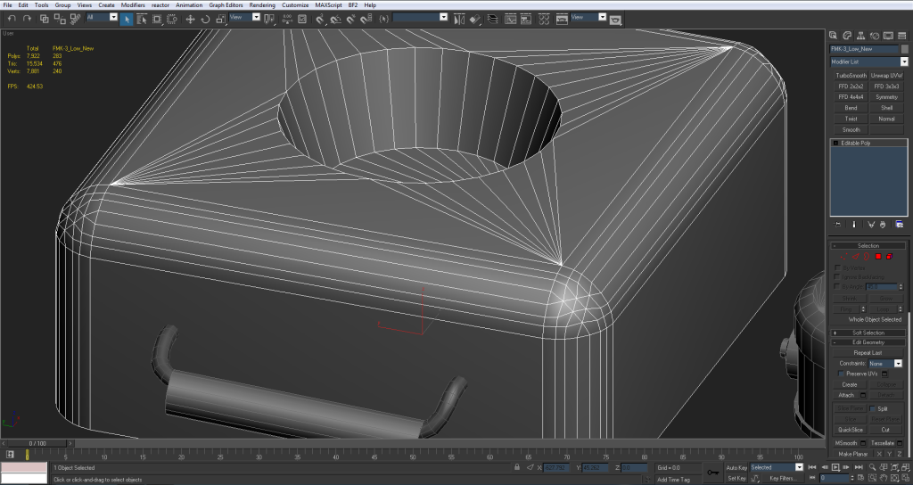
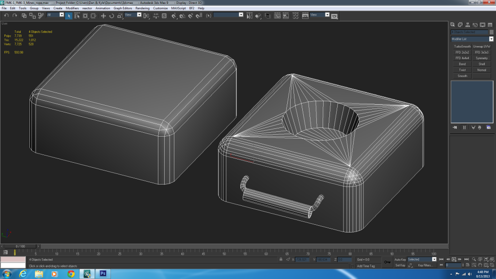
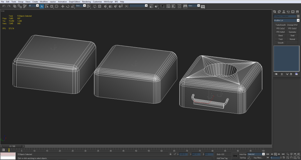
and a wireframe
I'm going to be gone from this for a week or so starting tomorrow and I'll pick it up when I get back. In the meantime let me know if you guys see anything that I missed or that can be changed on the low poly. (personally I think it's about finished ) and hopefully I can jump into UVing/ baking/ texturing this thing when I get back.
Thanks for the crits again. I've already learned a ton from just this model
EDIT: altogether 2,084 tris
Indeed, larger and has a bigger silhouette which you can more easily see etc.[/QUOTE]lucky.BOY" wrote:The handle should certaionly have more sides than the rope. While I agree that the number of sides the rope has can stay like this for 1p mesh, it should really be 6-8 for 3p mesh. But really give that handle more sides, about 16 should work. While the handle can be obscured by hand, animator may feel like showing it, so its best to give it same detail as rest of the thing, dont you think
Looking at the box, those chamfers on vertical corners could be a bit better. With round things like these corners are, you should try to chmafer it so the distance between each two edges is same. Alternative way to do round things with so many sides is to make a cylinder and weld quarter of it to the box
Got it
I also went ahead and shortened the FMK-1. It still looked too big in comparison to the FMK-3.
So here's everything all together:
and a wireframe
I'm going to be gone from this for a week or so starting tomorrow and I'll pick it up when I get back. In the meantime let me know if you guys see anything that I missed or that can be changed on the low poly. (personally I think it's about finished
Thanks for the crits again. I've already learned a ton from just this model
EDIT: altogether 2,084 tris
-
Rhino
- Retired PR Developer
- Posts: 47909
- Joined: 2005-12-13 20:00
Re: [WIP] FMK-1 & FMK-3 Mines (PR:F)
Looking good but as lucky said, you should work on your chamfering some more. This is just a quick one but more of what your aiming for:

-
3===SPECTER===3
- Posts: 831
- Joined: 2007-05-05 01:13
Re: [WIP] FMK-1 & FMK-3 Mines (PR:F)
Re-did the FMK-3 with more chamfers and a 32 sided interior cylinder
still have the old one tho
is this more along the lines of what you're talking about?
EDIT: just compared the two and this chamfering method def looks better than the old. It went from 420 to 470 tris but I feel its well worth it Now the only artifacts are in the sides but again, hopefully those can be cleared up by the normal map
still have the old one tho
is this more along the lines of what you're talking about?
EDIT: just compared the two and this chamfering method def looks better than the old. It went from 420 to 470 tris but I feel its well worth it
Last edited by 3===SPECTER===3 on 2013-07-30 04:23, edited 4 times in total.
-
lucky.BOY
- Posts: 1438
- Joined: 2010-03-03 13:25
Re: [WIP] FMK-1 & FMK-3 Mines (PR:F)
Looks better but there is still some room for improvement, as you really dont that many edges on there, you mainly need to keep your edges equally spaced apart. There really isnt any noticable difference in silhuette between yours and Rhino's, and he used like half the amount of edges you used. Plus I would say so many edges make the smoothing slightly worse imo. I certalny like the way you modelled the tips of the fmk3 better now, though
-
3===SPECTER===3
- Posts: 831
- Joined: 2007-05-05 01:13
Re: [WIP] FMK-1 & FMK-3 Mines (PR:F)
I would do it just like rhino's but for the life of me I can't figure out how he got 5 edges over an even numberlucky.BOY wrote:Looks better but there is still some room for improvement, as you really dont that many edges on there, you mainly need to keep your edges equally spaced apart. There really isnt any noticable difference in silhuette between yours and Rhino's, and he used like half the amount of edges you used. Plus I would say so many edges make the smoothing slightly worse imo. I certalny like the way you modelled the tips of the fmk3 better now, though
-
Rhino
- Retired PR Developer
- Posts: 47909
- Joined: 2005-12-13 20:00
Re: [WIP] FMK-1 & FMK-3 Mines (PR:F)
Sorry for the late reply didn't see this but I use the Quad Chamfer tool which is part of RappaTools33===SPECTER===3 wrote:I would do it just like rhino's but for the life of me I can't figure out how he got 5 edges over an even number
Dose cost a bit of money but most of the tools work with Max9 and that Chamfering tool, if you use it a lot like I do since I'm working on quite a lot of round objects, is well worth the money
BTW have you made any progress on this Spec?
-
3===SPECTER===3
- Posts: 831
- Joined: 2007-05-05 01:13
Re: [WIP] FMK-1 & FMK-3 Mines (PR:F)
Not since my last post, I'm still away on vacation till the end of this week but after that I'll be back on it
-
3===SPECTER===3
- Posts: 831
- Joined: 2007-05-05 01:13
Re: [WIP] FMK-1 & FMK-3 Mines (PR:F)
Sorry for the long delay guys, I had to get some PR 1.0 in after vacation
But I've been working on this a good bit too, doing some tests with the FMK-3. The way I see it that's the last little thing that needs to be optimized before I can move onto UVing this thing.
@Rhino those are some nice tools but unfortunately I'm in no position to pay for anything right now. Maybe some ways down the road that'll be very useful tho.
However I still did some tests chamfering the FMK-3 with less edges. The way I've been working these are really the only two options I can use; the 4 edged or the 8 edged chamfer.
The 8 edged gives a much nicer silhouette and the 4 edged looks a bit jagged. Overall the difference between them is only 132 tris.
Going with the theory that larger objects need more tris, I would personally keep it with the 8 sided chamfer. I think the only thing that needed fixing was the corners which I think came out a lot better
But I still wanted to see what you guys thought of the comparison between the two and maybe get the go ahead to start on the UVs.
But let me know what you guys think.
P.S. 1.0 is VERY well done and brought me back after a 2-3 year hiatus
But I've been working on this a good bit too, doing some tests with the FMK-3. The way I see it that's the last little thing that needs to be optimized before I can move onto UVing this thing.
@Rhino those are some nice tools
However I still did some tests chamfering the FMK-3 with less edges. The way I've been working these are really the only two options I can use; the 4 edged or the 8 edged chamfer.
The 8 edged gives a much nicer silhouette and the 4 edged looks a bit jagged. Overall the difference between them is only 132 tris.
Going with the theory that larger objects need more tris, I would personally keep it with the 8 sided chamfer. I think the only thing that needed fixing was the corners which I think came out a lot better
But I still wanted to see what you guys thought of the comparison between the two and maybe get the go ahead to start on the UVs.
But let me know what you guys think.
P.S. 1.0 is VERY well done and brought me back after a 2-3 year hiatus
-
Doc.Pock
- Posts: 2899
- Joined: 2010-08-23 14:53
Re: [WIP] FMK-1 & FMK-3 Mines (PR:F)
do you have any newer version of max that has bevel iterations? you could just import it there as OBJ and use that chamfer to get your result, then import back into max9
-
3===SPECTER===3
- Posts: 831
- Joined: 2007-05-05 01:13
Re: [WIP] FMK-1 & FMK-3 Mines (PR:F)
No all I have is 3dsMax9Doc.Pock wrote:do you have any newer version of max that has bevel iterations? you could just import it there as OBJ and use that chamfer to get your result, then import back into max9
I'm testing out a chamfer with 6 edges right now tho. It's harder to do but I can make it work. Do you guys think it's worth the trouble to optimize the 8 edged chamfer THAT much more?
-
3===SPECTER===3
- Posts: 831
- Joined: 2007-05-05 01:13
Re: [WIP] FMK-1 & FMK-3 Mines (PR:F)
Alright I just finished the 6-edged chamfer box and it really does come out better. I think that's the one I'm gonna use (the one in the middle)
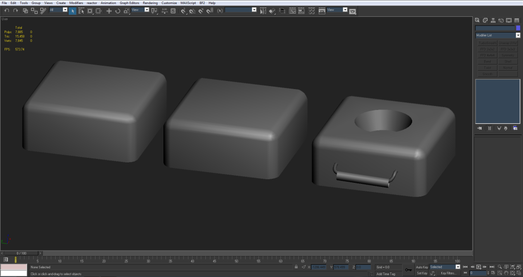
the only problem is that no matter which way I smooth it I still get some errors on the corners.
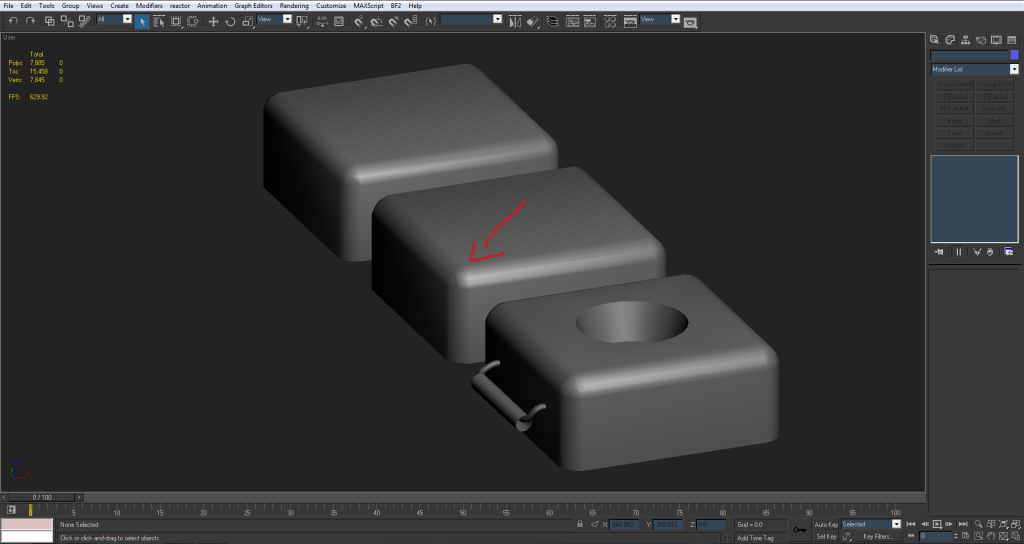
but hopefully the normal map can take care of that and it'll look fine with it applied.
let me know what you guys think, sorry for so many posts at once
the only problem is that no matter which way I smooth it I still get some errors on the corners.
but hopefully the normal map can take care of that and it'll look fine with it applied.
let me know what you guys think, sorry for so many posts at once
-
Doc.Pock
- Posts: 2899
- Joined: 2010-08-23 14:53
Re: [WIP] FMK-1 & FMK-3 Mines (PR:F)
every gradient can be fixed with the normal map. so dont worry about small stuff. ill show you how it works later
-
Rhino
- Retired PR Developer
- Posts: 47909
- Joined: 2005-12-13 20:00
Re: [WIP] FMK-1 & FMK-3 Mines (PR:F)
Just put all those faces on and around the chamfer on the same channel and then like pock says, the normal should sort out any tiny bits but you shouldn't actually have any smoothing problems there with this shape tbh.
-
Doc.Pock
- Posts: 2899
- Joined: 2010-08-23 14:53
Here is what i mean with normal map fixing gradients::
Box with one smoothing group, one iv island.

As you can see, gradients as vertex normals try to even out over harsh angles.
Highpoly and the box with normal map:

As you can se, the high poly's smoothing corrects the lowpolys, making it look quite good.
The normal map:

As ypu can see, normal map is fixing the gradients by introducing inverted gradients to make normals straight. This of course introduces the problem of editing and multiplying normal maps over themselves, but in your case, since you wont be doing it, and even if you would, its a small gradient that wouldnt matter.
Box with one smoothing group, one iv island.
As you can see, gradients as vertex normals try to even out over harsh angles.
Highpoly and the box with normal map:
As you can se, the high poly's smoothing corrects the lowpolys, making it look quite good.
The normal map:
As ypu can see, normal map is fixing the gradients by introducing inverted gradients to make normals straight. This of course introduces the problem of editing and multiplying normal maps over themselves, but in your case, since you wont be doing it, and even if you would, its a small gradient that wouldnt matter.
-
lucky.BOY
- Posts: 1438
- Joined: 2010-03-03 13:25
Re: [WIP] FMK-1 & FMK-3 Mines (PR:F)
Sorry for getting off topic, but wouldnt this go awfully wrong once you get down the mip chain, and pixel bleed starts kicking in?
On the actual topic, the 6 sided one looks great Specter, go with it
-
Doc.Pock
- Posts: 2899
- Joined: 2010-08-23 14:53
Re: [WIP] FMK-1 & FMK-3 Mines (PR:F)
dont think it would lucky. i mean mips are just downscaled textures and bleeding occurs on the edges, which have some padding anyway, so it should sta as it is
-
3===SPECTER===3
- Posts: 831
- Joined: 2007-05-05 01:13
Re: [WIP] FMK-1 & FMK-3 Mines (PR:F)
Thanks for the feedback guys. I went with the 6 edged chamfer box and am gonna call the low poly. In total its 2,048 tris.
Since then I decided to start on the UVs and have a few questions.
So far I've mapped every face to make sure the proportions are right and no UV's are backwards or anything.
On the FMK-1 I need to have a seam so I decided to put it on the back where it would be the least noticeable. (the side opposite the detonator)
The one problem is the 'cone' shaped hole where the detonator goes in.
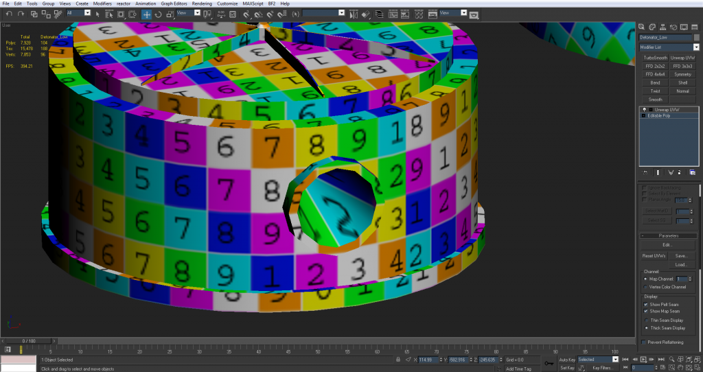
right now it's planar mapped and relaxed at 2000 iterations but still really distorted. Should I worry about it? since it's gonna be mostly black and small and also the detonator is going to be in there most of the time anyway.
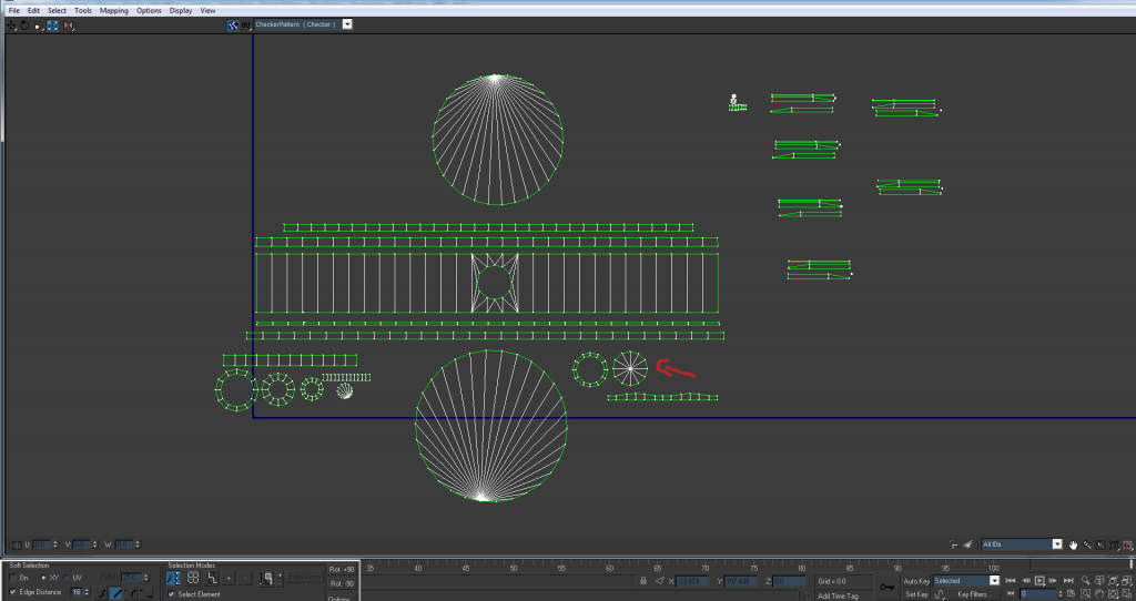
Here's the UV's for the base of the FMK-1
Detonator (seam is on the bottom)
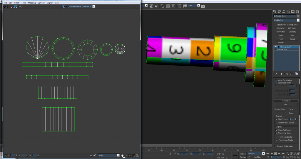
The top seems a little warped? (i can't really tell) on the sides but that's because I wanted the whole outside on the same smoothing group and in turn the same UV.
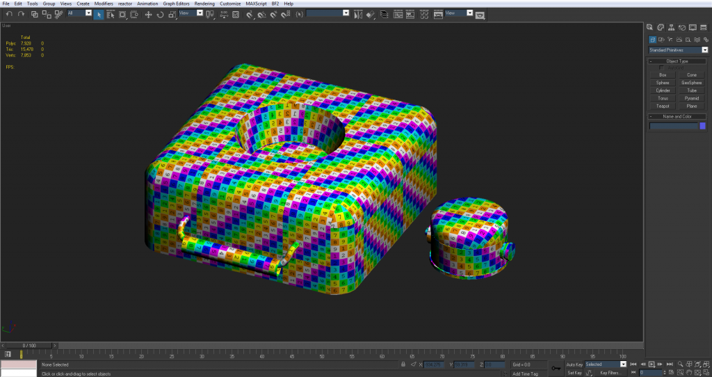
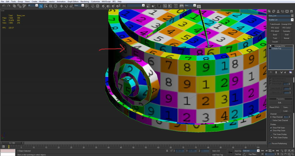
The biggest problem right now is the sides of the FMK-3
Right now the sides are detached from the main body because when I try to stitch them up they get warped a ton. I'd like to have them stitched to the main body and flattened together because they're on the same smoothing group and the seams would be pretty obviously seen. When they're stitched up I can try to manually relax them but for the most part they're always distorted.
Anyone have any suggestions for UVing this type of shape?
Or if the options are to choose between pixel distortion or seams which would be less noticeable?
Again thanks for the help guys
Since then I decided to start on the UVs and have a few questions.
So far I've mapped every face to make sure the proportions are right and no UV's are backwards or anything.
On the FMK-1 I need to have a seam so I decided to put it on the back where it would be the least noticeable. (the side opposite the detonator)
The one problem is the 'cone' shaped hole where the detonator goes in.
right now it's planar mapped and relaxed at 2000 iterations but still really distorted. Should I worry about it? since it's gonna be mostly black and small and also the detonator is going to be in there most of the time anyway.
Here's the UV's for the base of the FMK-1
Detonator (seam is on the bottom)
The top seems a little warped? (i can't really tell) on the sides but that's because I wanted the whole outside on the same smoothing group and in turn the same UV.
The biggest problem right now is the sides of the FMK-3
Right now the sides are detached from the main body because when I try to stitch them up they get warped a ton. I'd like to have them stitched to the main body and flattened together because they're on the same smoothing group and the seams would be pretty obviously seen. When they're stitched up I can try to manually relax them but for the most part they're always distorted.
Anyone have any suggestions for UVing this type of shape?
Or if the options are to choose between pixel distortion or seams which would be less noticeable?
Again thanks for the help guys
-
Rhino
- Retired PR Developer
- Posts: 47909
- Joined: 2005-12-13 20:00
Re: [WIP] FMK-1 & FMK-3 Mines (PR:F)
Sounds good, but remember you will ideally also want to do a 3p model and textures too once the textures are done for this but that sounds very good for the 1p model3===SPECTER===3 wrote:Thanks for the feedback guys. I went with the 6 edged chamfer box and am gonna call the low poly. In total its 2,048 tris.
Nothing wrong with UVs being backwards if it saves space, at least afaik and also not everything has to be in the same proportions for the final pack, stuff that wont be seen is best made smaller while stuff thats going to be really close to the player like Iron Sights on a weapon should have a much higher rez texture etc. Although yes before packing its good to layout everything in the same proportions3===SPECTER===3 wrote:So far I've mapped every face to make sure the proportions are right and no UV's are backwards or anything.
Yep that's good3===SPECTER===3 wrote:On the FMK-1 I need to have a seam so I decided to put it on the back where it would be the least noticeable. (the side opposite the detonator)
You just need to make the UV a bit bigger when it comes to packing, the bigger it is the less of a problem it will be although don't make it too big for something that will hardly be seen, just a bit bigger than it is now, using up some spare room on the packed UV3===SPECTER===3 wrote:The one problem is the 'cone' shaped hole where the detonator goes in.
right now it's planar mapped and relaxed at 2000 iterations but still really distorted. Should I worry about it? since it's gonna be mostly black and small and also the detonator is going to be in there most of the time anyway.
looks good but when it comes to packing you should put each UV inside each other, making the outer ones bigger for a small gap between which will overall mean more efficient use of space, even thou the larger objects are much bigger.3===SPECTER===3 wrote:Detonator (seam is on the bottom)
http://i1145.photobucket.com/albums/o51 ... e8490a.png
Looks totally fine to me. The only problem this really is afaik is if you are trying to paint absolute round details or something on the texture but I don't think you are in this case and for things like scratches its no problem to work with3===SPECTER===3 wrote:The top seems a little warped? (i can't really tell) on the sides but that's because I wanted the whole outside on the same smoothing group and in turn the same UV.
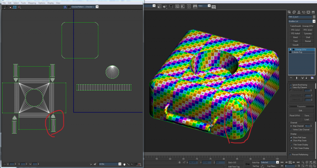
The best example I can quickly give you is how I did my Water Container VOIED's UVs which is a similar shape:3===SPECTER===3 wrote:The biggest problem right now is the sides of the FMK-3
Right now the sides are detached from the main body because when I try to stitch them up they get warped a ton. I'd like to have them stitched to the main body and flattened together because they're on the same smoothing group and the seams would be pretty obviously seen. When they're stitched up I can try to manually relax them but for the most part they're always distorted.

The important thing is to stitch up as much as you can IMO, as seams are far worse than a tiny bit of distortion which in most cases, you wont be able to notice and at the most will just make the texture artists life a bit harder, but nothing like as hard as trying to make seams match.
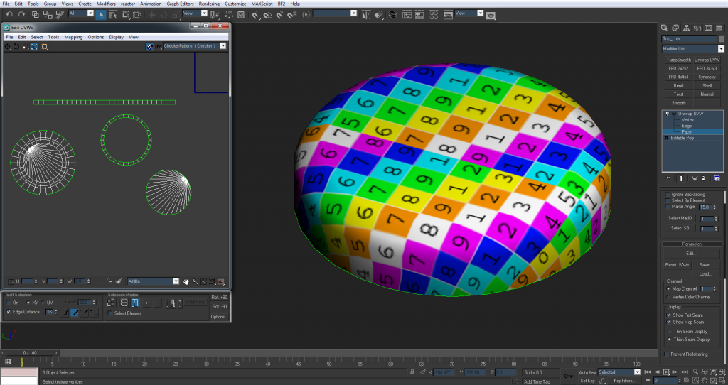
Basically what your looking at doing is doing as most stitching as you can, without distorting the UVs too much. A tiny bit is absolutely fine and well worth it:

Although with just the texture on above it looks totally fine, if we look at this same corner in checker we can see that its actually a tiny bit distorted:

The main thing like on this corner here is to split the UVs down the middle of chamfer where you need the seams to be and welding up the rest so you can get the most wleding for your money without having to affect too much, but where you can stitch these chamfers up, do so
But in your case, you won't be able to stitch the sides to each other with all of them being stitched to the top which is the main thing IMO, so you just need to split your chamfer UVs down the middle then stitch each side with the side they join onto
And keep the bottom UV of it separate as that will not get seen very much and on your main UV you can make it much smaller than the top UVs