[Question] How do YOU go about modeling a vehicle?

Making or wanting help making your own asset? Check in here
Post Reply
Clypp
Posts: 2148
Joined: 2006-07-17 18:36

[Question] How do YOU go about modeling a vehicle?

Post by Clypp »

I think I have run into far too many problems modeling the RG-31 Nyala and this may be due to my approach.

My approach:
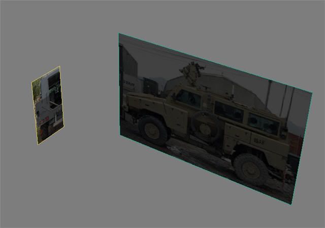
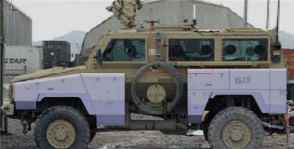
1. Made a plane the size (px) of my side reference image
2. Made a plane the size (px) of my rear reference
3. Placed references, offset back from the 0,0,0
Image
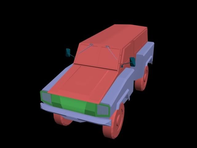
4. Made a plane 1x1 called rear fender. Made semi-transparent.
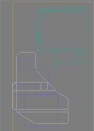
5. Converted plane to editable poly and added vertices on the lines to make it match the reference. For the little flaps that stick out I used a shift+scale.
6. Created the front fender the same way.
Image
7. Using the rear reference made the hull profile from a new plane -> editable poly.
8. Grabbed the edges of the fenders and dragged them back to the hull. Then using zoom and eyesight tried to line these vertices up with the hull's shape. Note, these are not attached in any way. I'm used to engineering modelers where this kind of approximation is liable to get you shot.
Image
9. Made the hood with a bunch of copied edges and some new edges vertices to vertices(This does not always seem to take though, often the second vertices cannot be grabbed)
Image
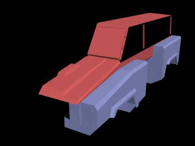
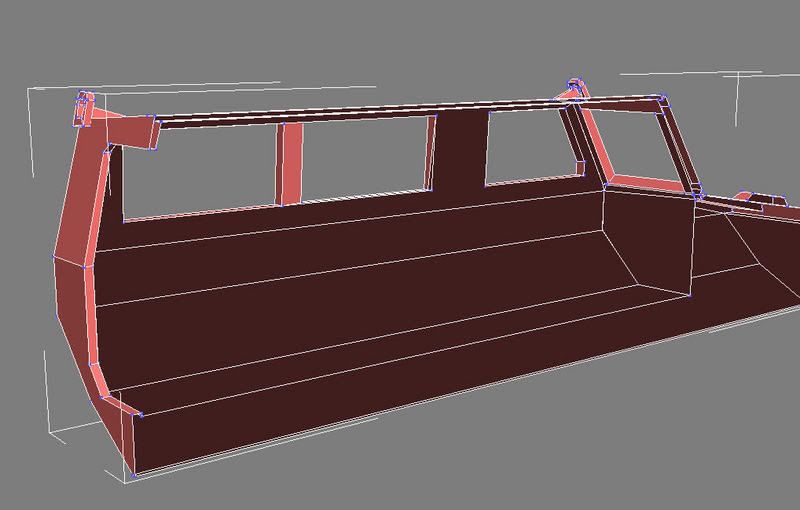
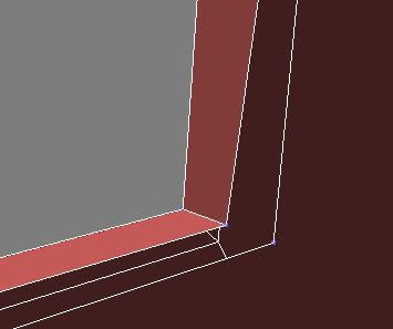
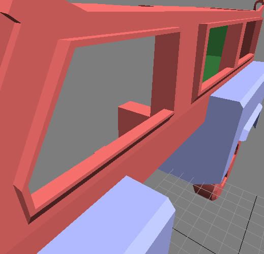
10.Attempted the side windows. Adding vertices to the existing plane did not work because they could not have edges created between. Then I tried copy+scale the edges around the plane I wanted to create the windows on. Then I copied+moved the edges out of the side of the vehicle to create the window frame. Only thing is, I cannot make new polies between these windows and the outsides of the side of vehicle-type plane. I have fought with this for many hours. The bridge tool seemed to help at first but it added overlapping planes. Why can't I just create a polygon like everywhere else? Because I get an error "Illegal new face"
Image
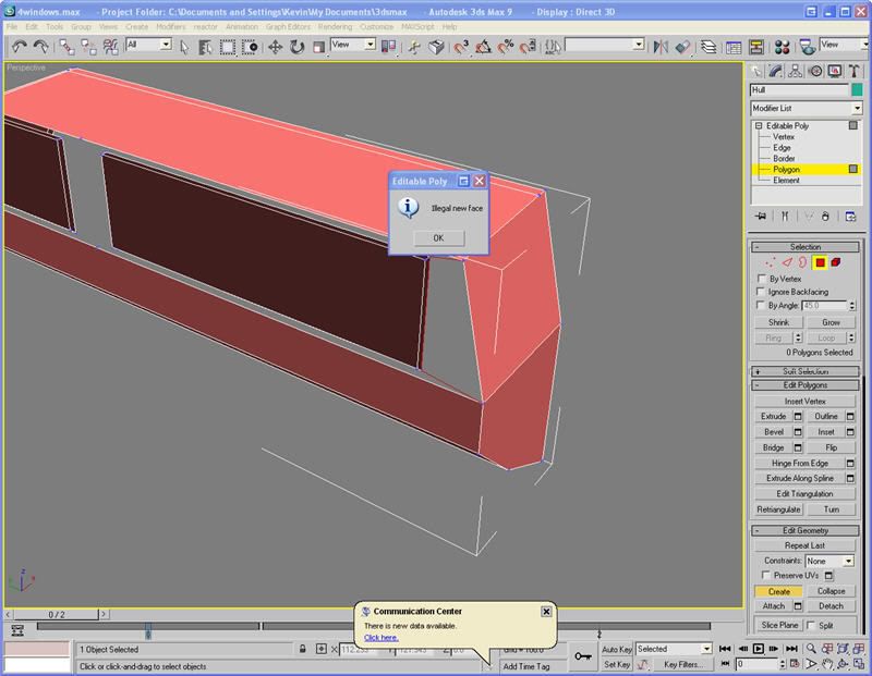
I'm really stuck here. Nothing works, though it probably a pretty simple problem, or I did it all crazy and out of whack that it boggles the mind. If you need more information I can provide it. Also, if you other modelers could give a brief description of your approach, that would be great.
Surround
Posts: 609
Joined: 2006-12-10 23:49

Post by Surround »

If you want to split one face into 2, you can use the great tool called Cut. You can make any type of shapes inside faces. Also you can try use Connect in Spline tools. It creates straight spline between two splines.

But for creating new faces you need atleast 3 vertex's and use the Create tool. More easy way is to select a spline and press Shift and copy the spline. It creates then a new face.

1 tip for easier modelling. Make a new material color you like (blue, red, green whaeva). Push the Autokey button. For the 1st frame, leave the Opacity 100%, but then for the second frame, put the Opacity of the Diffuse color somewhere between 50-70%. And for the 3rd frame, put the Opacity 0%. Push the Autokey off. After that go to Time Configuration settings and set the End frame to 2. After that you have 3 frames, 0,1 and 2. With buttons , and . you can change the frames which changes the opacity of the material. Oh yeah! Remember to drag the new material to the model ;)
Clypp
Posts: 2148
Joined: 2006-07-17 18:36

Post by Clypp »

I have been using that spline copy method. I called it edge+copy. I have also been using the transparency method with autokey. I learned that from that gun tutorial, very handy trick.

I have not had much success with cut, but I think I'll give it another shot to understand the tool since it seems to be used quite a bit.
-=NakedFrijoles=-
Posts: 3
Joined: 2007-05-24 02:05

Post by -=NakedFrijoles=- »

hm...this is kinda tricky to determine by the screen shots...couldnt u have used boolean or cut? and you are unable to delete everything on that side panel and then just create a single plane? if you can do that then just cut out the windows from that plane...seems like it should work.
Clypp
Posts: 2148
Joined: 2006-07-17 18:36

Post by Clypp »

OK, "Cut" officially kicks ***. Why did they hide it way down there on the sidebar?

Project is moving once again. I'm still interested in what strategies modellers with some experience have used. Cheeseman? Vaiski?Surround?
Desertfox
Posts: 5886
Joined: 2006-08-15 06:41

Post by Desertfox »

Clypp wrote:OK, "Cut" officially kicks ***. Why did they hide it way down there on the sidebar?

Project is moving once again. I'm still interested in what strategies modellers with some experience have used. Cheeseman? Vaiski?Surround?

I will get in contact with uncle_blues and see how his modeler did the humvee.
Image
Desertfox
Posts: 5886
Joined: 2006-08-15 06:41

Post by Desertfox »

Image
Cheeseman
Retired PR Developer
Posts: 1291
Joined: 2006-11-12 06:23

Post by Cheeseman »

Sorry, I haven't been active lately (my main computer's at repairs), but when I model I usually start off with my material. I find appropriate blueprints of what I'm modeling and I use photoshop to resize and cut the blueprints to even proportional sizes so that each blueprint side matches in size and dimension. After saving them as PNG format, I create a box in 3DS Max and I right click on move tool and open the move transform type-in to adjust its XYZ position to all 0 so my box is on center of grid. I then open material editor click on Standard to open Material/Map browser and I open Multi/Sub-Object. From there I click on Set Number and set my materials to the number of blueprint sides I have (Stryker I’m working on has 5). I then give each one a name (front, back, right, left, etc) by going from number 1 all the way to 5.
Hers how it should look like:
Image

Under Sub-Material on the same window click on the first material slot (being slot 1) and click on the little empty box seen in this picture:
Image

When you do click on that box, another window will open and you chose Bitmap before another window opens and you select your blueprint or picture to set as your material. Make sure you also click on the very top window toolbar and under the Material tab you select “Show map in viewport”. In the same page also make sure to scroll down to Bitmap Parameters and click on View Image. A new window should open with your image; right click on it to see the exact dimensions of it. Use these image sizes to configure your original boxes dimensions the same. Repeat this for all sides (depending on the number of reference blueprints or images you want to have).
Image

Once all sides are done, convert your box to editable poly. Under modify tab select Polygon; delete the sides you don’t have blueprints or images for and then select all the remaining sides and click Flip under Editable Polygons selection. This time select the polygon side you want on the box model and then scroll down to Polygon Properties in the modifier list and in the set ID box assign the ID number to the same side ID you have given your material in the Multi/Sub-Object (for me 1 being front, 2 being back, 3 being right, etc). Do this for all sides you have blueprints set in Multi/Sub-Object.

Image

Open Material Editor and drag and drop the sphere with your blueprints/images into the box. This should automatically assign each blueprint/image to each numbered side of the box. I just right click on my box with all the blueprints on it and go to Object Properties of it. From there I un-check Show Frozen in Gray and I check mark Backface Cull. I freeze the box with the blueprints and I make a new box and shape it in reference to the first box with all the blueprints or I make a plane and again modify it with segments, cutting, and extruding in reference to the first box. Sorry if I missed a few key points, but I’m in a hurry and not on my main computer.
Last edited by Cheeseman on 2007-08-09 22:00, edited 1 time in total.
Clypp
Posts: 2148
Joined: 2006-07-17 18:36

Post by Clypp »

Question update.

One issue I have encountered far too frequently is on with welding and face creation.

Image

I created the outer hull first, and then scale-copied to create the inside. Connecting the two peices at the windows is more of a challenge than I expected. When trying to create faces between the vertices I was unable to grab vertices from the copied part if I started at the outside part. So, I grabed the edges and pulled them in, however this is imperfect because I was only able to target weld in some corners, the other corners would not grab. This might have something to do with backfacing(?). Do I need to keep faces in mind for BF2 importing and skinning? I suppose I can flip them later if need be.

Image

Why is this? Is there an option or trickthat can fix this issue?

Sometimes when creating faces in editable poly I get the error "Illegal face". This means I have to either edgedrag-copy to fill the area and attempt to weld and this is less than ideal. What causes this peoblem, as far as I can tell in most cases I am planar so that is not the problem.

Image

Here is an early version of the Nyala when mirrored. I am a little further now.

Image

Please help.
Surround
Posts: 609
Joined: 2006-12-10 23:49

Post by Surround »

I made a video 4 u ;)
Sorry for bad engrish and ugly voice what you have to hear :D
http://www.youtube.com/watch?v=3W2TuwFXrnQ
Clypp
Posts: 2148
Joined: 2006-07-17 18:36

Post by Clypp »

Thanks so much Surround! That was very nice of you.

After messing with the windows a little more I found that bridge DOES work however the plane is twisted to look like an X. This must be result of the faces being backwards in the inside of the vehicle. Since I copied by grabbing faces and scaling I cannot run "Normal" because this would reverse faces on all of my Hull portion. How do I flip normals on just a selection of planes?
Surround
Posts: 609
Joined: 2006-12-10 23:49

Post by Surround »

Well, If you havent gone very far I would suggest start again from the scale copy thing.


Edit: In the Edit poly tools theres a Flip tool in the polygons.

Edit poly-> Polygons-> Edit polygons-> Flip just select a polygon and press flip
Clypp
Posts: 2148
Joined: 2006-07-17 18:36

Post by Clypp »

OK, new issue. How the heck to you create windows? you can only have so many poly's coming from a single vertex. I need to keep the insides of the frame there else you will see inside the wall of the vehicle through the transparent glass.

I wish there was a button in max that was called, "Just do it."
Clypp
Posts: 2148
Joined: 2006-07-17 18:36

Post by Clypp »

Bump for attention.
Surround
Posts: 609
Joined: 2006-12-10 23:49

Post by Surround »

Can u send a pic ref what you mean. My english isnt so good that it would be me to understand you. AAARgh! Just look at that sentence <----- Speake with pics and thou shall be replied.
Clypp
Posts: 2148
Joined: 2006-07-17 18:36

Post by Clypp »

Image
I want a window in that frame. This would consist of 2 planes, or a special window block(?). I can't do planes because no more poly surfaces can be welded to the corner vertices.
Post Reply

Return to “PR:BF2 Community Modding”